Scientists in Spain have proposed a new way to calculate the structural shadow factor and mismatch losses for the rear of bifacial PV modules with the help of trackers of one axis. They tested the new methodology in a real PV system and discovered that it is able to establish a linear fit based on distance to the coupling tube.
Researchers from the Spain’s Technical University of Madrid (IES-UPM) have proposed a new method to determine the Shading Factor (SSF) and Misml loss structure (MML) (MML) for the rear of Bifacial PV modules using an-as trackers.
In their experimental analysis, the team both considered one-in-portrait (1P) setups, whereby the coupling tube runs directly behind the center of the panel, as well as two-in-portrait (2p) setups, where the coupling tube is between the two panels.
“The calculation of SSF and MML is important for two reasons. First, the input parameters are required by PV simulation software for Energy Persons Estimations. PV -Magazine. “This uncertainty control is crucial for industrial and financial participants, whose greatest care is the limitation of financial risks related to bifacial PV systems. Secondly, they are usually asked from Tracker manufacturers by EPCs and other stakeholders of the PV industry.”
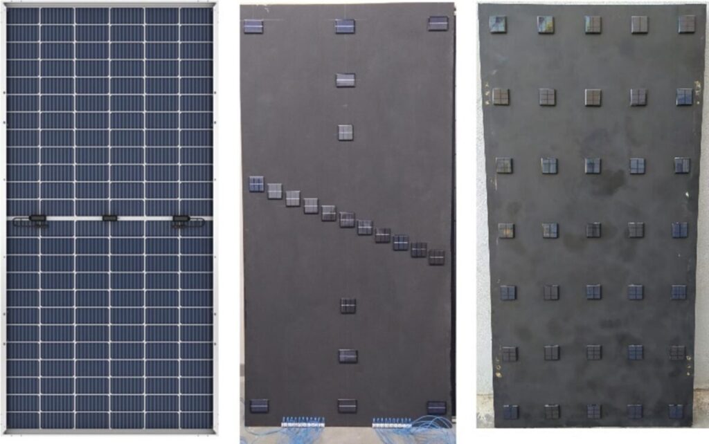
To determine experimental SSF and MML, the group has designed two instruments with high spatial resolution rear radiation cards at the module level. For a 1P setup they used a wooden board with dimensions 2 mx 1 m, on which 21 solar cells were placed strategically. The instrument for the 2P measurement was comparable in size, but included 35 cells uniform divided into five columns and seven rows. “It creates a high spatial resolution rear radiation cards measured at the module level,” said Merodio.
The proposed methodology was tested in a PV factory in Cheste, Spain, including 1p and 2P trackers equipped with 355 WP Bifacial Longi Solar. The soil is covered with gravel, where Albedo is approximately 30%. The connecting tubes have a square section of 14 cm x 14 cm. The tracker heights were 1.35 m for the 1p and 2.1 m for the 2P, and the array widths were 2 m for the 1p and 4.16 m for the 2P, which gives a ratio to width of 0.7 for the 1p and 0.5 for the 2p.
Image: Universidad Politécnica de Madrid (IES-UPM), Solar Energy, CC by 4.0
Based on the measurements of the instruments, the group developed calculations for SSF and MML. To calculate SSF, they suggested comparing how much sunlight the back of the panel receives with and without shadow of the structure. To calculate MML, on the other hand, they used a formula that connects uneven sunlight with power loss. “It must be set for drawing conclusions from these comparisons, because the SSF and MML parameters are highly dependent on the specific characteristics of the PV system that they describe,” they emphasized.
Testing showed that SSF is 10.0% for 1P trackers and MML is 0.46% for full-cell modules and 0.40% for semi-cell modules. For 2P trackers, SSF is 2.7% and MML is 0.35% and 0.21% for full-cell semi-cell modules respectively. “We also offer a linear fit of SSF as a function of the distance (D) from the connecting tube to the PV module: SSF = -0.2D+11.6. Equivalente linear relationships are found for MML, taking into account full cell, mml = -0.02d+0.62 and half -cellmodules Academics said.
“The uncertainty in SSF associated with our measurement procedure is estimated at 4%(2%) for the 1P (2P) tracker, while the uncertainty in MML is expected to be a maximum of 4%for both trackers,” they concluded. “When our results are used as constant annual inputs for estimates of the energy yield, these uncertainties must be adjusted to 10% in SSF for both trackers and 20% (30%) in mml for the 1P (2P) tracker, but their impact on the uncertainty in the energy return has not been reduced to a few gemetis. MML values. “
Their findings were presented in “Experimental determination of the structural shadow factor and mismatch losing for bifacial photovoltaic modules on variable geometry, trackers with one axis,“Published in Solar energy. According to Dr. Merodio is now working the team on expanding their measuring campaign into cloudy days and studying “second-order effects, such as the shadow caused by the pillars and the tracking system mechanisms, as well as edge effects on modules at the end of a tracker.”
This content is protected by copyright and may not be reused. If you want to work with us and reuse part of our content, please contact: editors@pv-magazine.com.
Popular content


